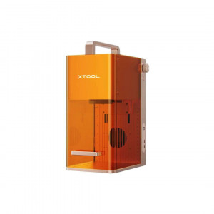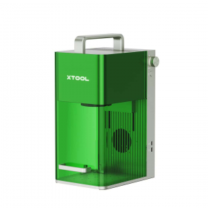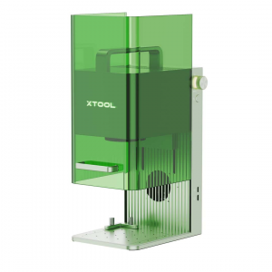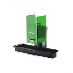
- Stock: In Stock
- Product code: 920372000001160195
- Weight Brutto: 16.00kg
- SKU: P0102000083

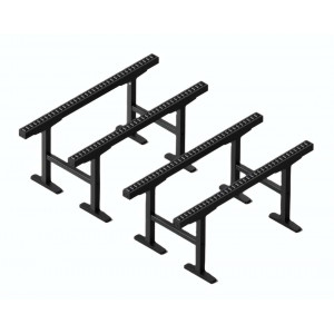
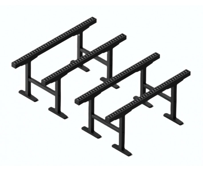
The xTool P3 Conveyor Rail is a modular material-support extension engineered exclusively for the xTool P3 automatic conveyor feeder, enabling continuous long-format processing without repositioning. The kit delivers 4 conveyor rail sets, 8 height-adjustable support leg assemblies, 4 cross-frame support beams, and all required mounting hardware to extend the P3's effective feed path on both the infeed and outfeed sides simultaneously.
| Compatible System | xTool P3 with automatic conveyor feeder (installed) |
|---|---|
| Conveyor Rails Included | 4 pcs |
| Support Legs + Bases | 8 + 8 pcs (height-adjustable) |
| Fastener Set | M3×6 ×32, M4×6 ×8 |
The photograph below shows the correct material-feeding configuration in action: a wood panel slides from the external conveyor rail surface into the xTool P3's internal processing zone, flush and co-planar throughout the full panel length.
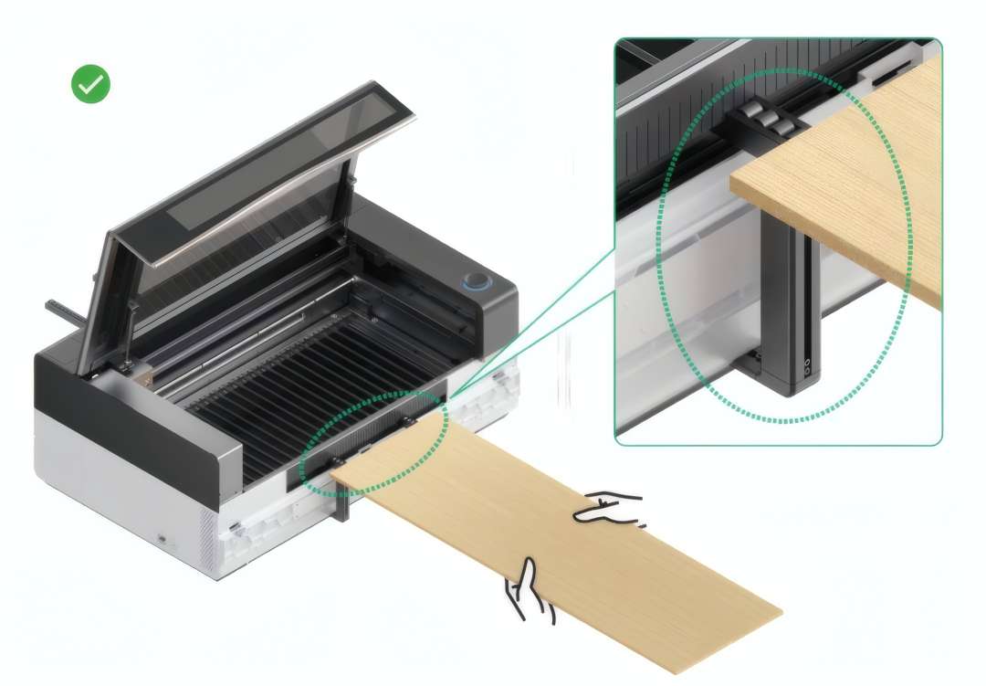
Process Long Panels and Boards Without Interruption
When working with sheet materials longer than the xTool P3's internal processing area, the standard single-zone configuration forces operators to stop mid-job, reposition the workpiece, and re-register the job origin — losing time and risking seam misalignment. The Conveyor Rail eliminates this entirely. With the rail frame in place on both sides of the machine, the automatic conveyor feeder advances material through the laser path in a single uninterrupted pass. Long boards, acrylic sheets, and roll stock feed straight in, get processed, and exit cleanly on the other side.
Modular Ladder-Frame Construction
The kit assembles into two parallel rail units — one on each side of the P3. Each unit consists of 2 conveyor rails bridged by 2 support beams, creating a ladder-frame structure with defined lateral rigidity. Eight T-shaped support leg assemblies carry the rails at adjustable heights. No permanent fixtures: the entire frame is screwed together using only the included M3 and M4 hardware. The diagram below shows the fully assembled frame aligned with the xTool P3 on both sides, with a detail callout highlighting where the external rail surface meets the machine's internal conveyor rails.
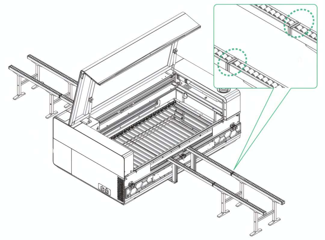
Height Adjustment for Flush Interface with the P3's Internal Rails
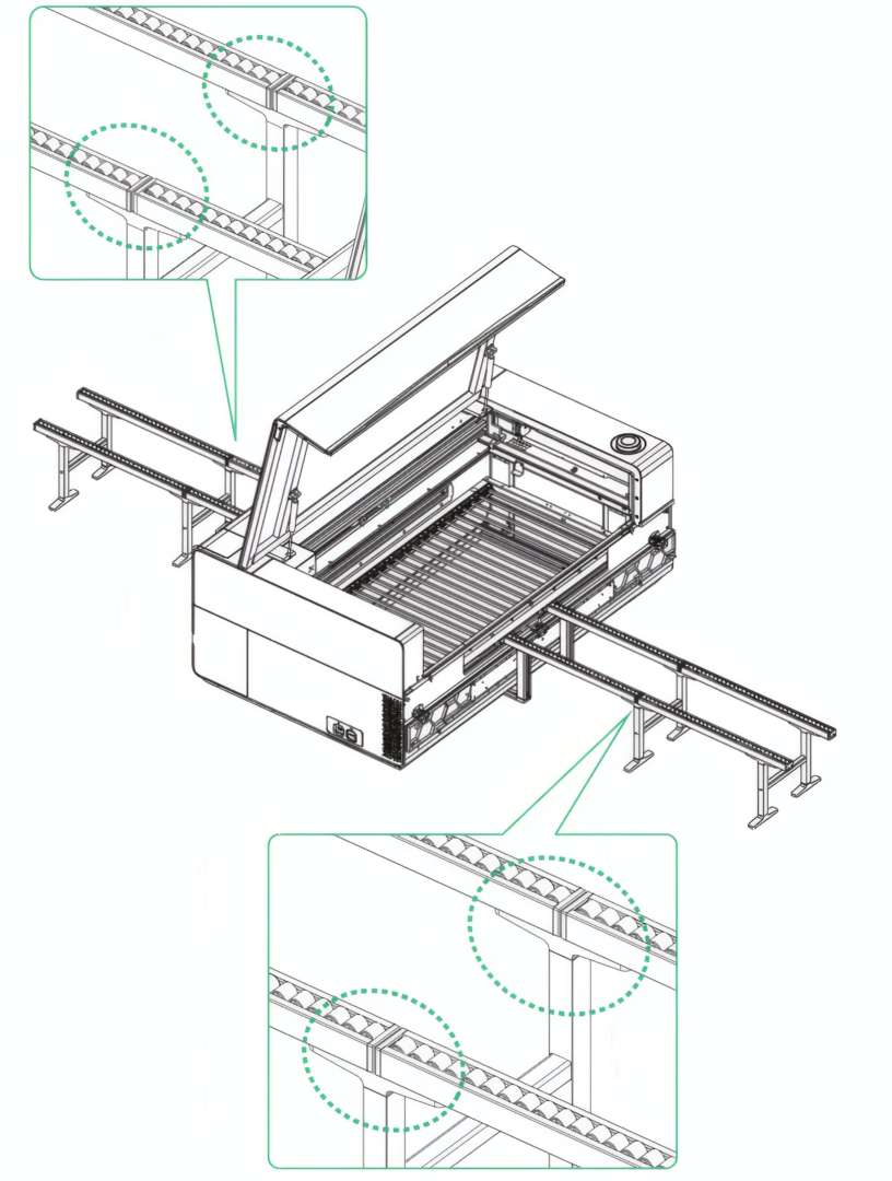
The most critical dimension in any conveyor extension is the height match between the external rail surface and the machine's internal rail surface. Each support leg is independently adjustable: raise or lower individual legs until the external rail sits flush with the P3's internal rails at the entry and exit points. The assembly documentation specifies that both rail sets must close contact with the machine's internal rails — any height step at the interface will cause material to catch, skew, or advance at an angle.
Leveling Protocol: Flat Surface, Consistent Cut Depth
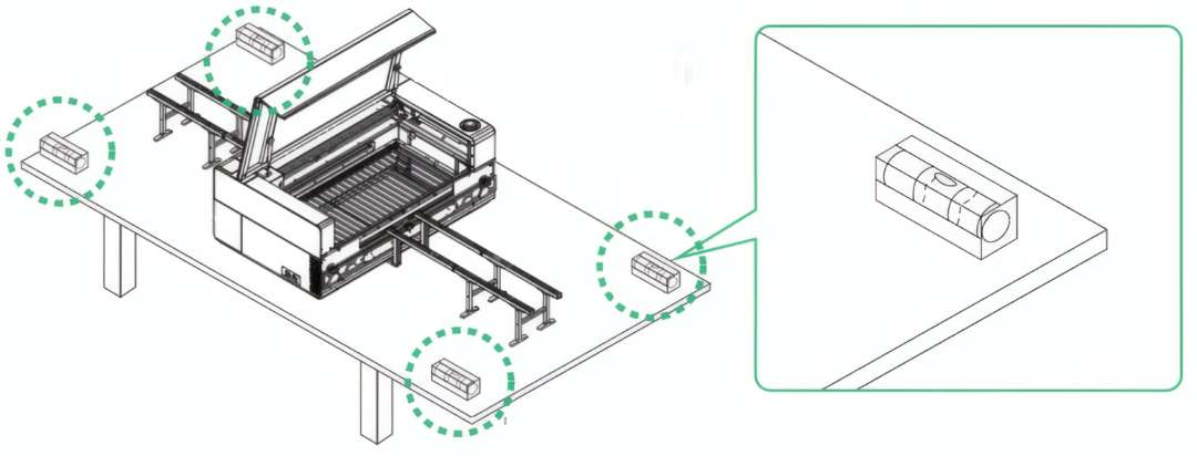
A rail surface that tilts by even 1–2 mm along its length creates a focus offset at the far end of a long panel, producing inconsistent engraving depth or an incomplete cut at one edge. The included level tool confirms whether the rail surfaces are flat. Use it before every session when the frame has been moved or reassembled. The illustration below identifies the recommended check positions: at each support leg base contact point on the table surface.
Post-Load Adjustment: Compensate for Material Thickness
A 3 mm or 6 mm sheet loaded on the conveyor rails sits higher than the unloaded surface. If the two parallel rail sets do not carry the sheet at the same height, the material bows slightly at the machine entry point — enough to affect focus and alignment. Load a test piece across both rail sets and the internal rails, then adjust each support leg until the sheet lies flat across the full span. The close-up diagram below shows both the input-side and output-side adjustment check points to confirm even height on both ends.
Technical Specifications of the xTool P3 Conveyor Rail
Compatibility
| Compatible Machine | xTool P3 |
|---|---|
| Required Prerequisite | xTool P3 automatic conveyor feeder must be installed before use |
| Feed Direction Requirement | Rail orientation must be parallel to the material feed direction |
Package Components
| Conveyor Rail | ×4 |
|---|---|
| Support Leg | ×8 |
| Support Leg Base | ×8 |
| Support Beam | ×4 |
| Screw M3×6 | ×32 |
| Screw M4×6 | ×8 |
| User Manual | ×1 |
Frame Configuration
| Support Leg Height | Adjustable |
|---|---|
| Number of Frame Units | 2 (infeed side + outfeed side) |
| Rails per Frame Unit | 2 |
| Surface Flatness Verification | Level tool included |
What's in the Box
- Conveyor rail ×4
- Support leg ×8
- Support leg base ×8
- Support beam ×4
- Screw M3×6 ×32
- Screw M4×6 ×8
- User manual ×1
How to Assemble the xTool P3 Conveyor Rail
This procedure covers full mechanical assembly of the xTool P3 Conveyor Rail — from individual components to a leveled, material-ready configuration positioned alongside the xTool P3 laser cutter. Ensure the xTool P3 automatic conveyor feeder is already installed in the machine before beginning.
Step 1: Assemble the First Support Leg Unit
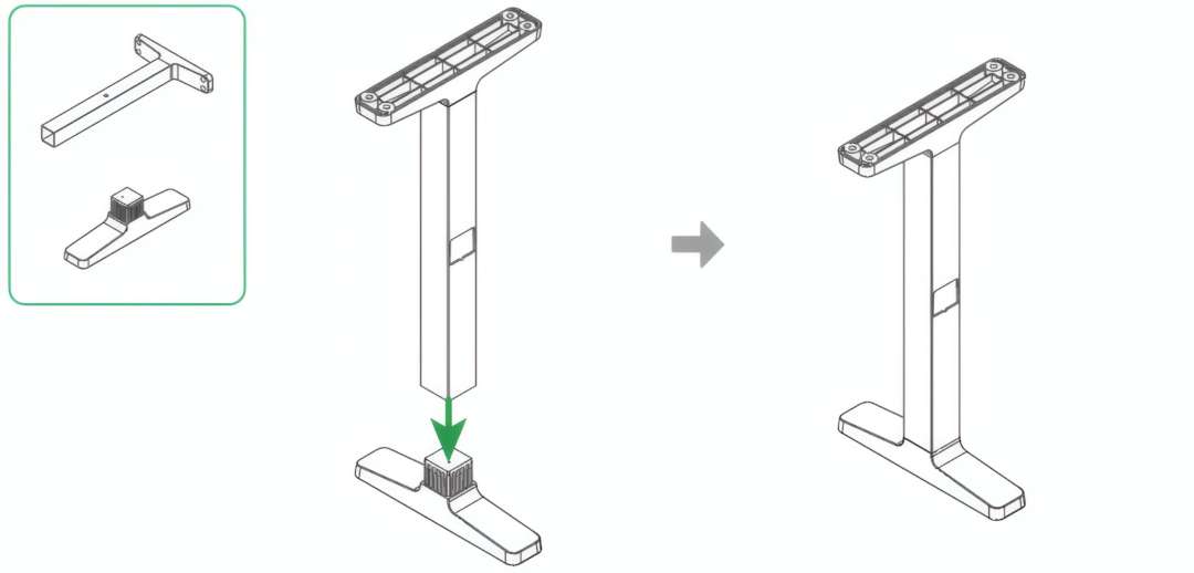
Take one T-shaped support leg and one rectangular support leg base. Confirm the base orientation — the wider flat face must be down. Insert the post of the support leg into the receiving slot on the base and press until the connection is firm. The assembly diagram below shows the two components before joining (with a green directional arrow) and the completed unit side by side.
Step 2: Complete All Eight Support Leg Units
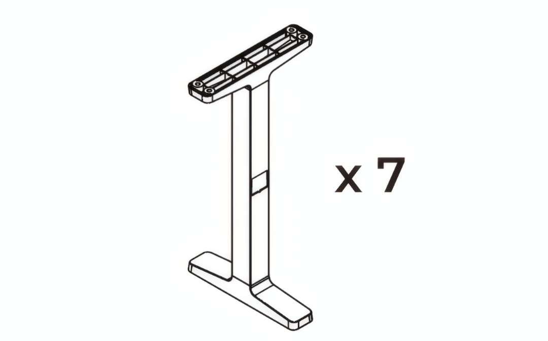
Repeat the process from Step 1 for the remaining 7 leg-and-base pairs. All 8 units must be assembled before moving to rail attachment. The illustration below confirms the target quantity — the single assembled unit shown represents the same assembly to be repeated 7 more times.
Step 3: Lay Out Parts for the First Rail Assembly
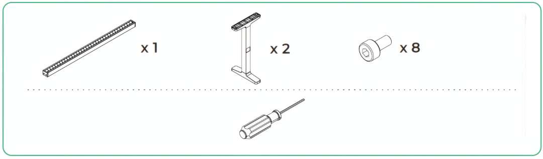
For each of the 4 conveyor rails, collect: 1 conveyor rail, 2 assembled support leg units, and 8 screws from the feeder hardware pack. Stage all components for one rail set before starting to avoid mixing fasteners between sets. The parts diagram below shows exactly what is needed for a single rail assembly, including the screwdriver.
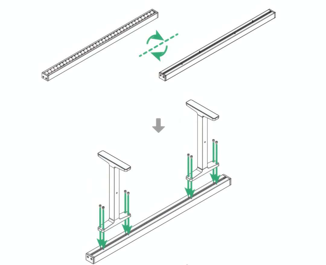
Step 4: Attach Support Legs to the Conveyor Rail
Orient the conveyor rail with the correct face up — note the rotation arrows in the diagram indicating proper rail orientation. Position two assembled support leg units beneath the rail at the designated mounting holes near each end. Drive 8 screws through the mounting points to secure the rail to the leg heads. The assembly diagram below shows the screw insertion direction and the final attached configuration.
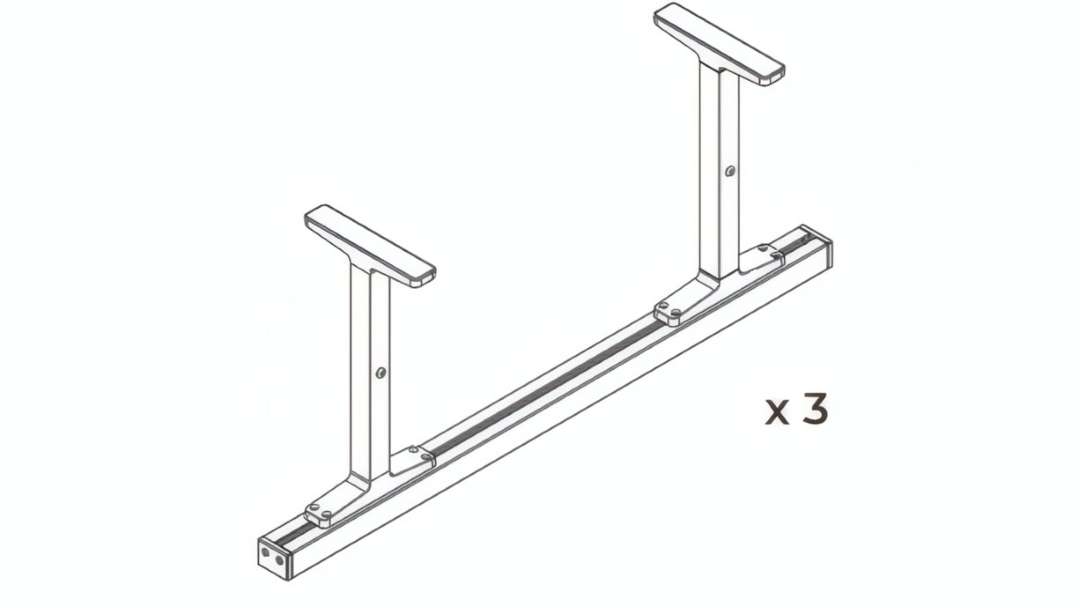
Step 5: Assemble the Remaining Three Rail Sets
Repeat Steps 3–4 for the three remaining conveyor rails. Each receives 2 support leg units and 8 screws. After this step you will have 4 identical individual rail sets — each a horizontal rail carried on two T-leg assemblies. The illustration below shows one completed set; produce 3 more matching units.
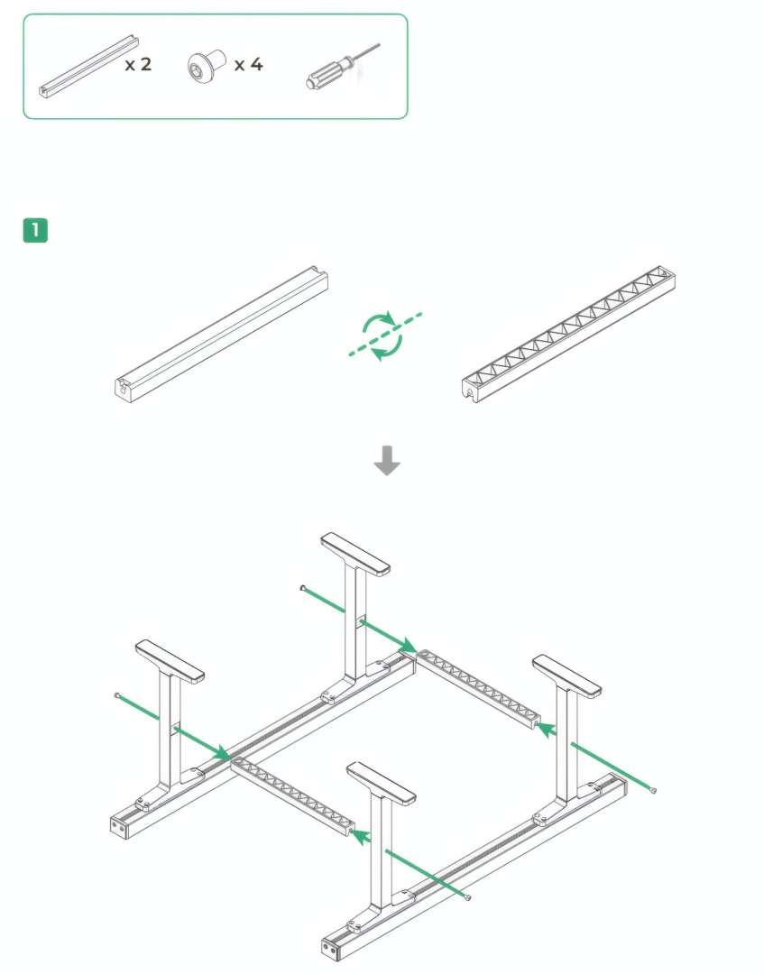
Step 6: Connect Two Rail Sets with Support Beams
Take 2 rail sets, 2 support beams, and 4 screws. Position the two rail sets parallel to each other at the correct spacing, both upside-down (legs pointing up). Insert the support beams between the two rails at the designated beam slots. Orient beams with the triangulated lattice face inward. Drive 4 screws to lock the beams in place. The assembly diagram below shows the beam insertion sequence for the first pair.
Step 7: Turn the Sub-Assembly Right-Side Up
With the support beams secured, the sub-assembly is currently inverted — legs pointing upward. Carefully flip the entire frame over so the support legs stand on the surface and the conveyor rail faces point upward. The before/after diagram below shows the inverted assembly on the left and the correctly oriented standing frame on the right.
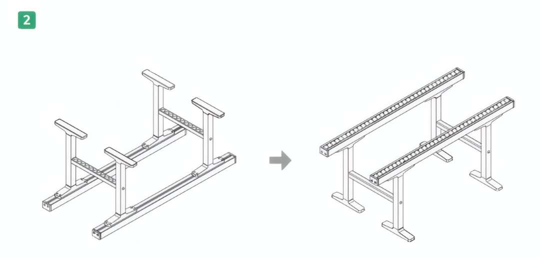
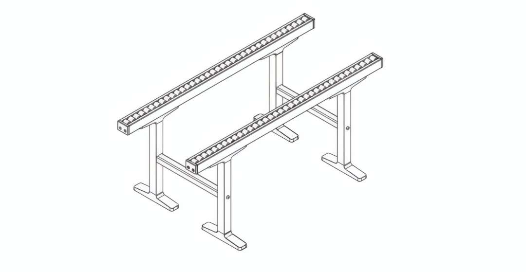
Step 8: Assemble the Second Frame Unit and Verify the Complete Structure
Repeat Steps 6–7 with the remaining 2 rail sets, 2 support beams, and 4 screws to produce a second identical frame unit. Both frame units are now mechanically complete. The isometric view below shows the finished assembly: two parallel rail sets per unit, each carried on T-leg assemblies and braced by cross-beams, ready to be positioned on both sides of the xTool P3. Proceed to position, align, and level the frame as described in the product alignment section.
Is the xTool P3 Conveyor Rail compatible with other xTool machines?
No. The xTool P3 Conveyor Rail is designed exclusively for use with the xTool P3. Additionally, the xTool P3 automatic conveyor feeder must be installed in the machine before the Conveyor Rail can function. It is not compatible with other xTool laser cutter models.
How many conveyor rail sets are included, and how are they arranged?
The package includes 4 conveyor rails. They assemble into two frame units of 2 rails each — one unit is placed on the infeed side of the xTool P3, and one on the outfeed side. This dual-side configuration supports the full length of long workpieces both before they enter and after they exit the laser processing zone.
Does assembly require tools beyond what is included in the package?
No additional tools are required. The package includes all M3×6 and M4×6 screws needed for full assembly, a screwdriver, and a level tool for surface flatness verification.
How do I confirm the conveyor rails are level and correctly aligned?
Use the included level tool on the rail surface at multiple points — checking near each support leg base is recommended. A centered bubble indicates a flat surface. If the two frame units are not at the same height, adjust the support legs individually until the surfaces are co-planar. After loading test material, verify the sheet lies flat across both external rails and the machine's internal rails with no step or bow at the entry point.
Where can I find operating instructions for processing with the Conveyor Rail?
Full operating and processing instructions are available at support.xtool.com/article/2064. This resource covers software configuration for continuous conveyor-based jobs and material feed parameter setup for the xTool P3.
Why Choose EXPERT3D?
EXPERT3D has specialised in advanced laser technology, 3D printing, and digital fabrication since 2012 — over a decade of hands-on experience selecting, deploying, and supporting professional-grade equipment across makerspaces, design studios, and production facilities. As an official representative of xTool, we guarantee the best price, authorized service, and official warranty. We provide pre-sales technical consultation, fast delivery coordination across Spain and Europe, and direct post-sale support backed by manufacturer contacts. Contact us to discuss your specific workflow requirements and current availability.