


- Stock: In Stock
- Product code: FSCAN-TRAK-PRO2
- Weight Brutto: 28.00kg
- SKU: FSCAN-TRAK-PRO2
FreeScan Trak Pro2 is a portable optical coordinate measuring system built for markerless 3D scanning of medium-to-large industrial parts, delivering metrology-grade accuracy of 0.023 mm and a scan speed of up to 3 070 000 points/s. Powered by dual-camera dynamic referencing and 50 blue laser lines, it eliminates the need to place physical markers on the workpiece — saving preparation time across aerospace, automotive, and heavy-manufacturing quality-control workflows.
| Parameter | Value |
|---|---|
| Accuracy | 0.023 mm (0.0009 in) |
| Scan speed | Up to 3 070 000 points/s |
| Max. field of view | 650 × 580 mm |
| Accuracy certification | VDI/VDE 2634 Part 3, ISO 10360 (ISO 17025 accredited lab) |
Markerless Dynamic Tracking: Faster Setup, Cleaner Workflow
Traditional optical scanning demands dozens — sometimes hundreds — of adhesive reflective markers stuck to the part surface. The FreeScan Trak Pro2 replaces that entire step with the FreeTrak optical tracking bar. Mounted on a tripod, FreeTrak uses infrared LEDs and a dual-camera system to track the position of the handheld TE25 laser scanner in real time, so the coordinate system stays locked to the part geometry rather than to physical markers.
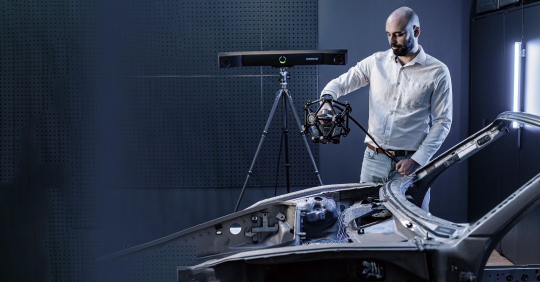
The result is twofold: you spend less time preparing the part, and you avoid marker-related alignment issues on curved, dark, or reflective surfaces. When the scan scenario requires it — for instance, multi-view stitching on very large assemblies — the system also supports a conventional marker-based mode, giving you full flexibility.
Three Laser Modes for Every Surface Condition
Not every geometry responds well to a single scan pattern. The TE25 scanner ships with three selectable light-source modes, each optimised for a different use case:
- 50 crossed laser lines — maximum coverage for rapid data acquisition on large, open surfaces.
- 7 parallel laser lines — partial HD mode that captures extremely fine surface detail on small or complex zones.
- 1 single laser line — deep-hole scanning with a hole-diameter-to-depth ratio of 1 : 4, reaching cavities that crossed-line patterns cannot enter.
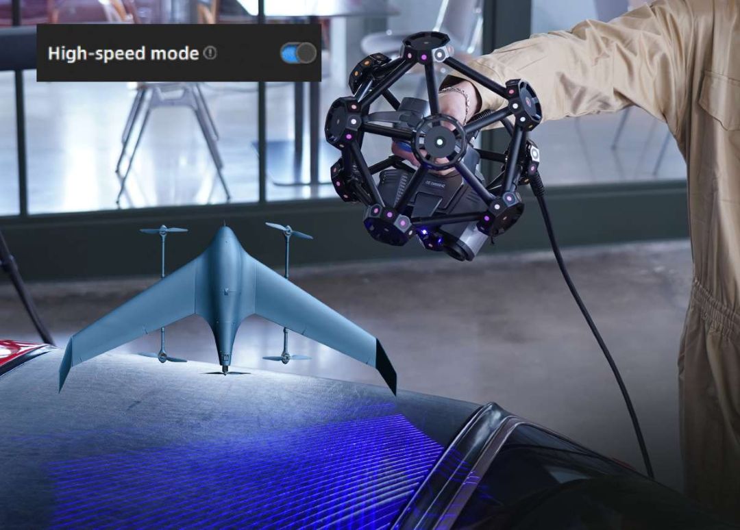
Paired with two 5.0 MP industrial cameras, the 50-line mode drives data capture at up to 3 070 000 points/s, converting hours of manual measurement into minutes of continuous scanning.
Metrology-Grade Accuracy at 0.023 mm
Accuracy is not a marketing claim here — it is certified. The FreeScan Trak Pro2 is evaluated according to VDI/VDE 2634 Part 3 and ISO 10360 standards, with sphere-spacing error assessed using traceable length artefacts inside an ISO 17025 accredited laboratory (temperature 20 ± 0.5 °C, humidity 40–60 % RH).
Volumetric accuracy holds strong across large working volumes: 0.062 mm within 9.6 m³ and 0.072 mm within 17.6 m³. When combined with photogrammetry, the system reaches 0.044 mm + 0.012 mm/m, making it suitable for first-article inspection and GD&T verification on aerospace and automotive components.
Expandable Tracking Volume for Large Assemblies
The maximum field of view per scan frame is 650 × 580 mm, but the effective working volume extends far beyond that. The FreeTrak bar supports three tracking-volume tiers:
- H 1 635 mm × W 2 045 mm
- H 2 540 mm × W 3 000 mm
- H 3 090 mm × W 3 702 mm
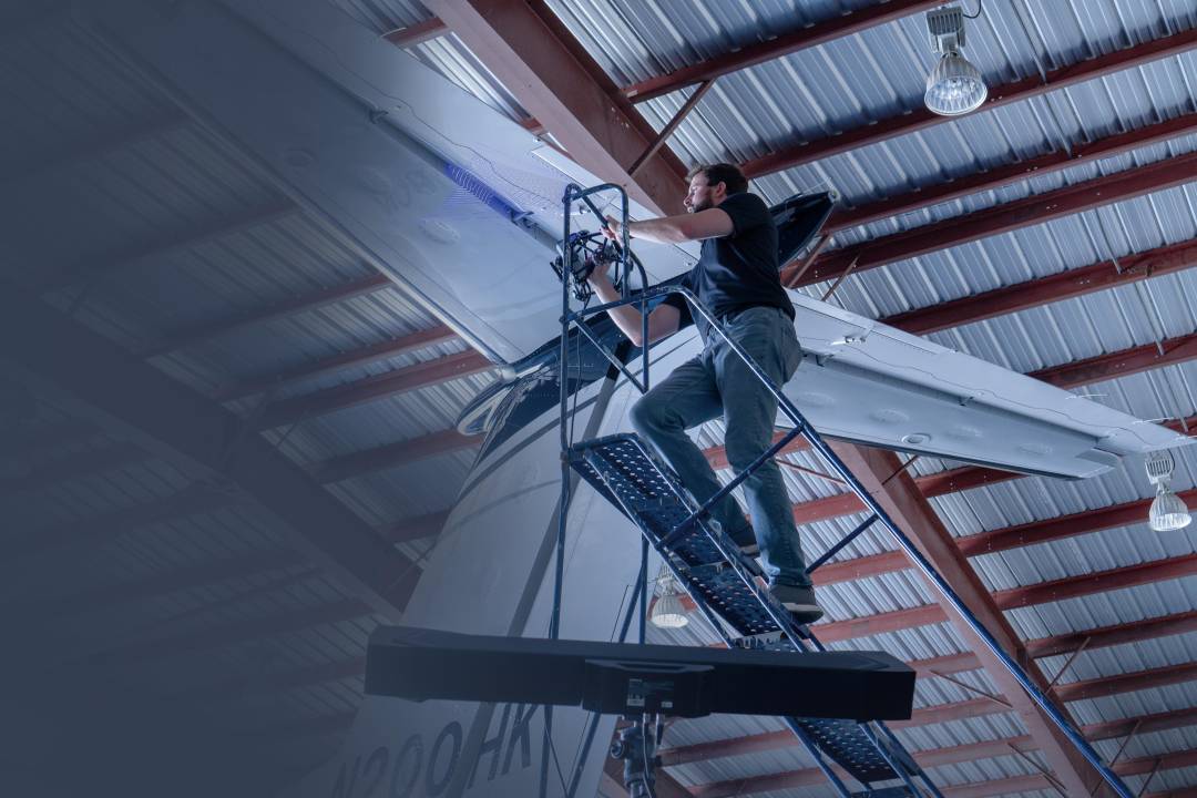
This eliminates the need for leapfrogging — the traditional technique of repositioning the measuring device and re-referencing artefacts — across the majority of medium-to-large parts, including car body panels, aircraft skin sections, and industrial tooling.
FreeProbe: Optional Contact Probing Integration
When specific dimensional features need point-based measurement — hole centres, slot widths, datum planes — the optional FreeProbe adds contact-probe capability to the same coordinate system. With an accuracy of 0.025 mm and a measurement rate of 100 points/s, the probe integrates directly with PolyWorks and Geomagic Control X for quick inspection workflows.
The ergonomic handle, multifunctional button, and ruby measuring tip allow the operator to switch between optical scanning and contact probing without recalibrating the coordinate frame.
Real-Time Meshing and Data Quality Visualisation
The bundled software generates mesh data in real time as you scan, removing the post-scan point-cloud-to-mesh processing step. A colour-coded data-quality indicator overlays directly onto the 3D model: blue regions indicate complete data, while yellow sections flag areas where additional scanning passes are needed.
Scanning-distance feedback is equally intuitive — the colour of the projected laser lines changes from blue (too far) through green (optimal) to red (too close), so the operator maintains the correct working distance by visual reference alone.

Tech Tip: Always warm up the scanner for approximately 15 minutes before calibration. The manual recommends reaching a stable device temperature of about 35 °C to ensure accuracy and precision. If the device has not been calibrated for more than 7 days, the software will prompt you to recalibrate — do not skip this step if accuracy-critical measurements are planned.
Technical Specifications of the FreeScan Trak Pro2
Accuracy and Performance
| Accuracy | 0.023 mm (0.0009 in) |
|---|---|
| Volumetric accuracy (9.6 m³) | 0.062 mm (0.0024 in) |
| Volumetric accuracy (17.6 m³) | 0.072 mm (0.0028 in) |
| Volumetric accuracy with photogrammetry | 0.044 mm + 0.012 mm/m (0.0017 + 0.0004 in/ft) |
| Scan speed | Up to 3 070 000 points/s |
| Max. field of view (FOV) | 650 × 580 mm (25.5 × 22.8 in) |
| Point distance | 0.01 – 10 mm (0.0003 – 0.39 in) |
| Scan depth | 400 mm (15.7 in) |
| Recommended object size | 0.1 – 10 m (3.937 – 393.7 in) |
Physical Specifications
| Weight (FreeTrak) | 7.2 kg (15.8 lbs) |
|---|---|
| Weight (TE25 scanner) | 1.47 kg (3.2 lbs) |
| Dimensions (FreeTrak) | 1 079 × 237 × 110 mm (42.4 × 9.3 × 4.3 in) |
| Dimensions (TE25 scanner) | 281 × 283 × 290 mm (11.1 × 11.1 × 11.4 in) |
Light Source and Laser
| Light source (FreeTrak) | Infrared LED |
|---|---|
| Light source (TE25) | 50 cross laser lines, 7 parallel laser lines, 1 single laser line |
| Laser class | Class II |
Connectivity and Environment
| Working distance | 300 mm (11.8 in) |
|---|---|
| Connectivity | USB 3.0, IEEE 802.11n/ac, IEEE 802.3ab |
| Output formats | .stl, .asc, .3mf |
| Operating temperature range | -10 – 40 °C (14 – 104 °F) |
| Operating humidity range | 10 – 90 % RH |
Certifications
| Certifications | CE, FCC, ROHS, WEEE, KC, FDA, UKCA, IP50, TELEC, TISAX |
|---|---|
| Accuracy certification | VDI/VDE 2634 Part 3, ISO 10360 (ISO 17025 accredited lab) |
FreeProbe (Optional)
| FreeProbe accuracy | 0.025 mm (0.0009 in) |
|---|---|
| FreeProbe measurement speed | 100 measurements/s |
| FreeProbe weight | 0.5 kg (1.1 lbs) |
| FreeProbe dimensions | 70 × 150 × 340 mm (2.7 × 5.9 × 13.3 in) |
Recommended Computer Configuration
| Operating system | Windows 11 Professional 22H2 (64-bit) |
|---|---|
| Processor | 13th Gen Intel Core i7-13700H or above |
| Graphics card | NVIDIA GeForce RTX 4060 or above |
| Video memory (VRAM) | 8 GB or above |
| RAM | 64 GB or above, DDR5 dual-channel |
| USB port | USB 3.0 |
How to Set Up the FreeScan Trak Pro2
Step-by-step hardware connection and first-time calibration procedure for the FreeScan Trak Pro2 system.
Step 1 — Mount the FreeTrak Tracking Bar
Install the FreeTrak optical tracker on a stable tripod and tighten the mounting bolts securely. Position the tripod so the tracking bar has a clear line of sight to the area you intend to scan.
Step 2 — Connect All Cables via the Hub
Connect one end of the tracker cable to the FreeTrak and the other end to the hub. Repeat with the scanner cable for the TE25. Connect the hub power cable to a power outlet, and the data cable from the hub to your computer's USB 3.0 port. Insert the software authorisation Dongle into a spare USB port.
Step 3 — Install and Activate the Software
Copy the installer to your PC and run it with administrator privileges. After installation, launch the software and log in with your Shining3D account to activate the device. For offline activation, export the C2SN3D file, activate via passport.shining3d.com, and import the resulting SN3D2C file.
Step 4 — Calibrate the System
Allow the scanner to warm up to approximately 35 °C (about 15 minutes). Follow the on-screen calibration wizard: first calibrate the tracker using the calibration rod, then the scanner using the calibration board, and finally the system calibration using the system calibrator. The software will confirm successful calibration and skip this step on subsequent launches.
Step 5 — Select Scan Mode and Begin Scanning
Create a new project group, then select Trak Mode for markerless scanning or Laser Mode for marker-assisted scanning. Choose the appropriate light-source mode (50 lines, 7 lines, or 1 line) based on your part geometry, adjust brightness, and press the scan button on the TE25 to begin data acquisition.
What's in the Box
- FreeTrak I-G1 optical tracking bar
- FreeScan TE25 handheld laser scanner
- Hub (connects tracker, scanner, and PC)
- Tracker cable
- Scanner cable
- Hub power cable and power adapter (24 V, 3.75 A)
- Data cable (USB 3.0)
- Software authorisation Dongle
- Calibration board with flannel bag
- Calibration rod
- System calibrator
- Tripod
Frequently Asked Questions
Does the FreeScan Trak Pro2 require markers on the scanned object?
No. In Trak Mode the FreeTrak optical tracking bar dynamically tracks the TE25 scanner using its built-in infrared targets, so no physical markers need to be placed on the workpiece. A traditional marker-based mode is also available in Laser Mode for situations where markers provide an advantage.
What is the maximum object size the FreeScan Trak Pro2 can measure?
The recommended object size ranges from 0.1 m to 10 m. For objects larger than the standard tracking volume, the tracking range can be expanded up to 3 090 × 3 702 mm, and photogrammetry mode can stitch multiple capture zones into a single coordinate frame.
How often should the scanner be calibrated?
Calibration is required on first use, after the device has been idle for one to two weeks, after transportation involving significant vibration, or whenever you notice a drop in accuracy such as frequent alignment failures. The software alerts you if more than seven days have passed since the last calibration.
Can the FreeScan Trak Pro2 scan reflective or dark surfaces?
Yes. The scan settings include a reflective-object mode that can be toggled directly from the scanner buttons. For challenging surfaces the brightness slider and the choice of light-source mode (50 lines, 7 lines, or 1 line) help optimise data capture quality.
What third-party inspection software is compatible?
Scan data can be exported in .stl, .asc, and .3mf formats. The software integrates directly with Geomagic Control X (2023), PolyWorks Metrology Suite (2023–2025), Geomagic Design X (2020), Geomagic Essentials (2023), and EXModel for reverse engineering.
What are the minimum PC requirements to run the scanner software?
The manufacturer recommends Windows 11 Professional 22H2 (64-bit), a 13th-generation Intel Core i7-13700H processor or above, an NVIDIA GeForce RTX 4060 graphics card with 8 GB VRAM or above, 64 GB DDR5 dual-channel RAM, and a USB 3.0 port. Reserve at least 15 GB of free storage on the system and installation drives.
Why Choose EXPERT3D?
EXPERT3D has been supplying professional 3D scanning, 3D printing, and additive-manufacturing solutions from Valencia since 2012. With over a decade of hands-on experience in metrology-grade hardware, our team provides technical consultation, commissioning support, and after-sales service across Spain and Europe. Whether you are evaluating the FreeScan Trak Pro2 for an aerospace QC line or an automotive reverse-engineering cell, we help you integrate the right tool into your workflow — and keep it running at peak accuracy.


")